IPS deployment in IDS mode
One of the options in IDS mode is to use network TAP devices that copy packets for the IPS engines.
In an IPS Cluster, all nodes must receive all packets. The nodes agree over the heartbeat link which node inspects which connections.
Figure: Single IPS in IDS mode with a network TAP

Figure: IPS Cluster in IDS mode with network TAPs

Figure: Single IPS in IDS mode with a network TAP and an interface for sending resets
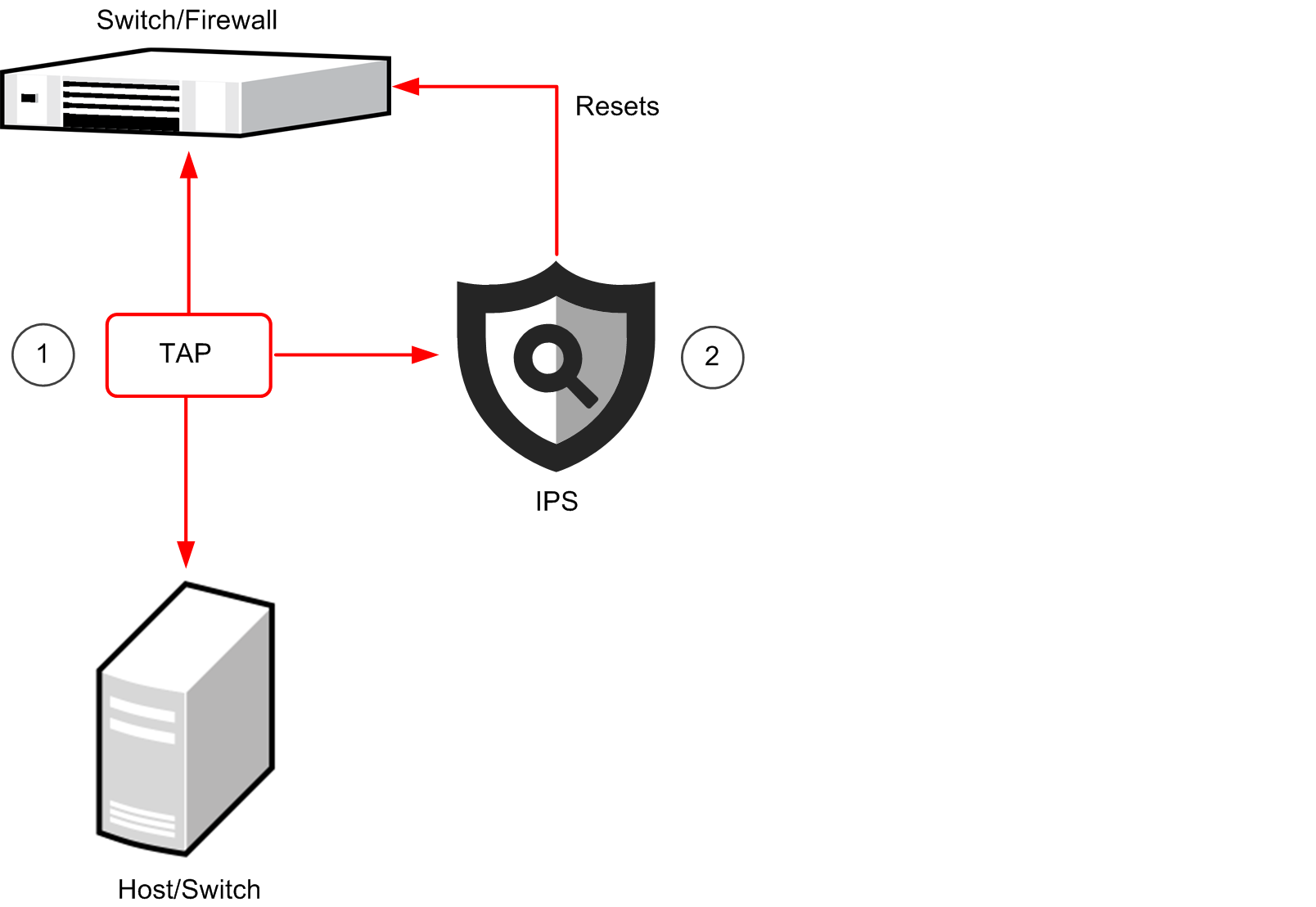
- 1
- A pattern in captured traffic triggers the reset.
- 2
- IPS sends a reset within the same broadcast domain to each communicating host posing as the other host by using its IP address and MAC address.
Figure: IPS Cluster in IDS mode with network TAPs on a redundant link
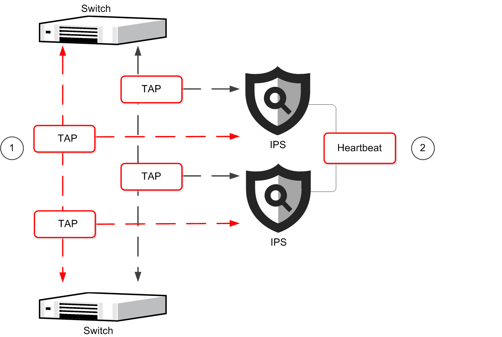
- 1
- Switches balance traffic across redundant links.
- 2
- Links are combined into a Logical Interface to inspect whole connections.
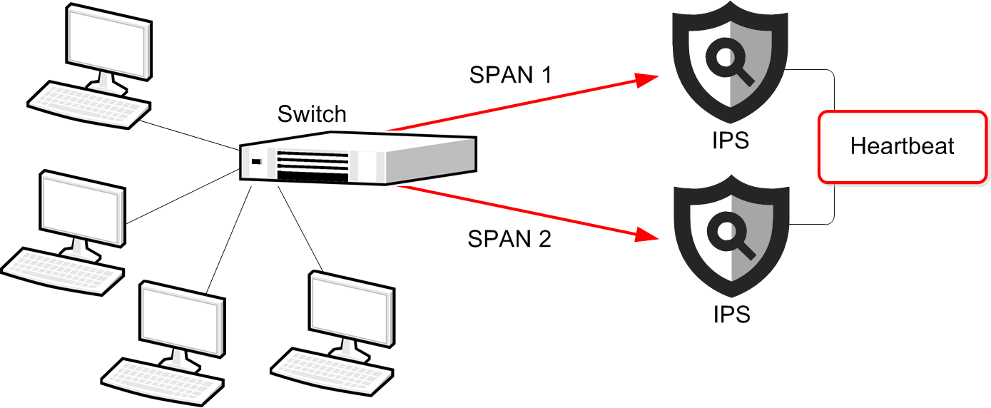
Packets can also be duplicated for inspection through a SPAN or mirror port on a switch/router. In an IPS Cluster, each node must be connected to a SPAN or mirror port of its own. Hubs are not recommended, but you can use hubs in configurations where the low performance of a hub is not an issue. For example, in a basic testing environment.
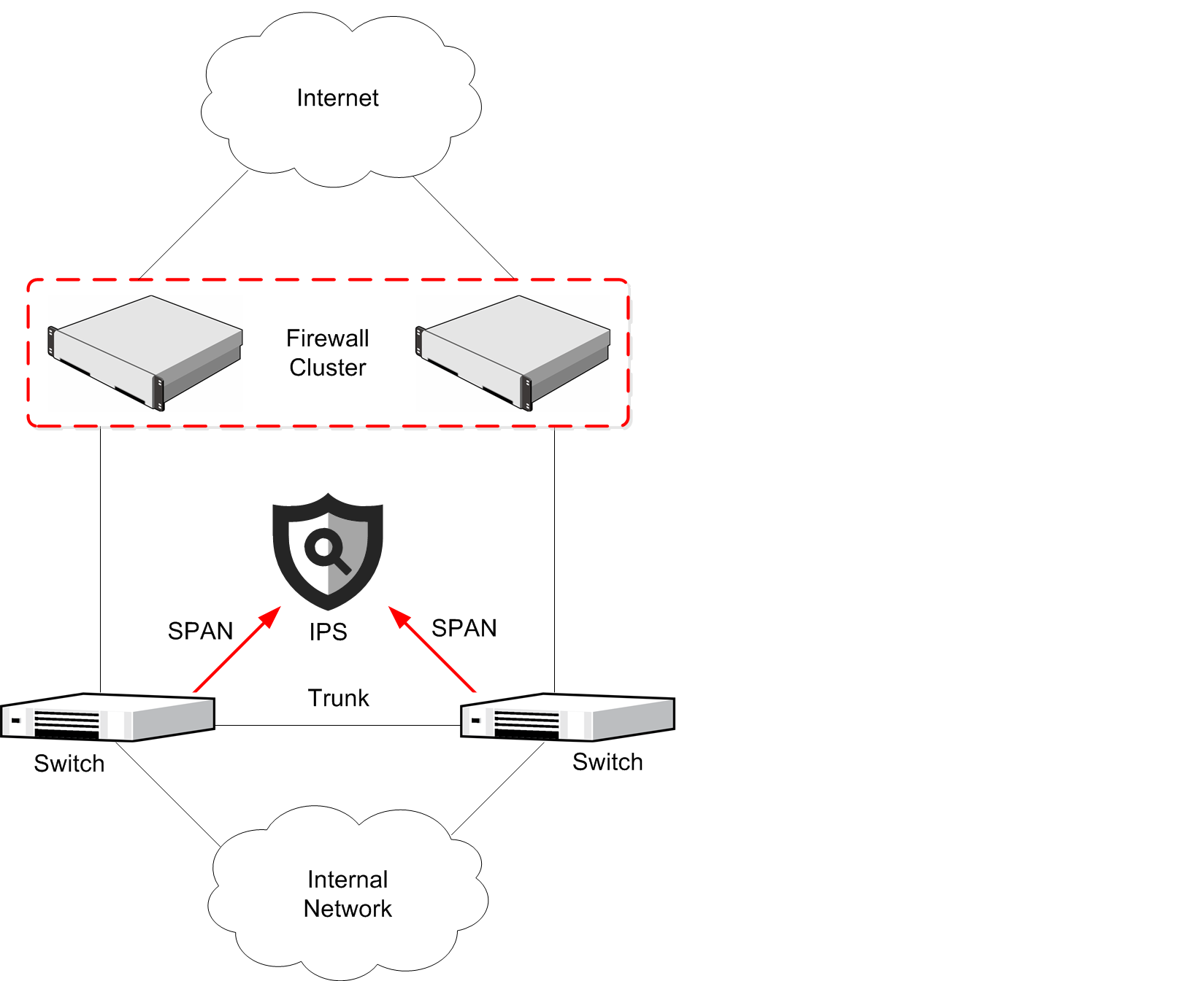
Figure: IPS Cluster in IDS mode with SPAN/mirror ports
An IPS Cluster can be deployed alongside a Firewall Cluster. In this configuration, the IPS Cluster is in the same broadcast domain as the Firewall.
Figure: IPS connected to SPAN ports alongside redundant switches
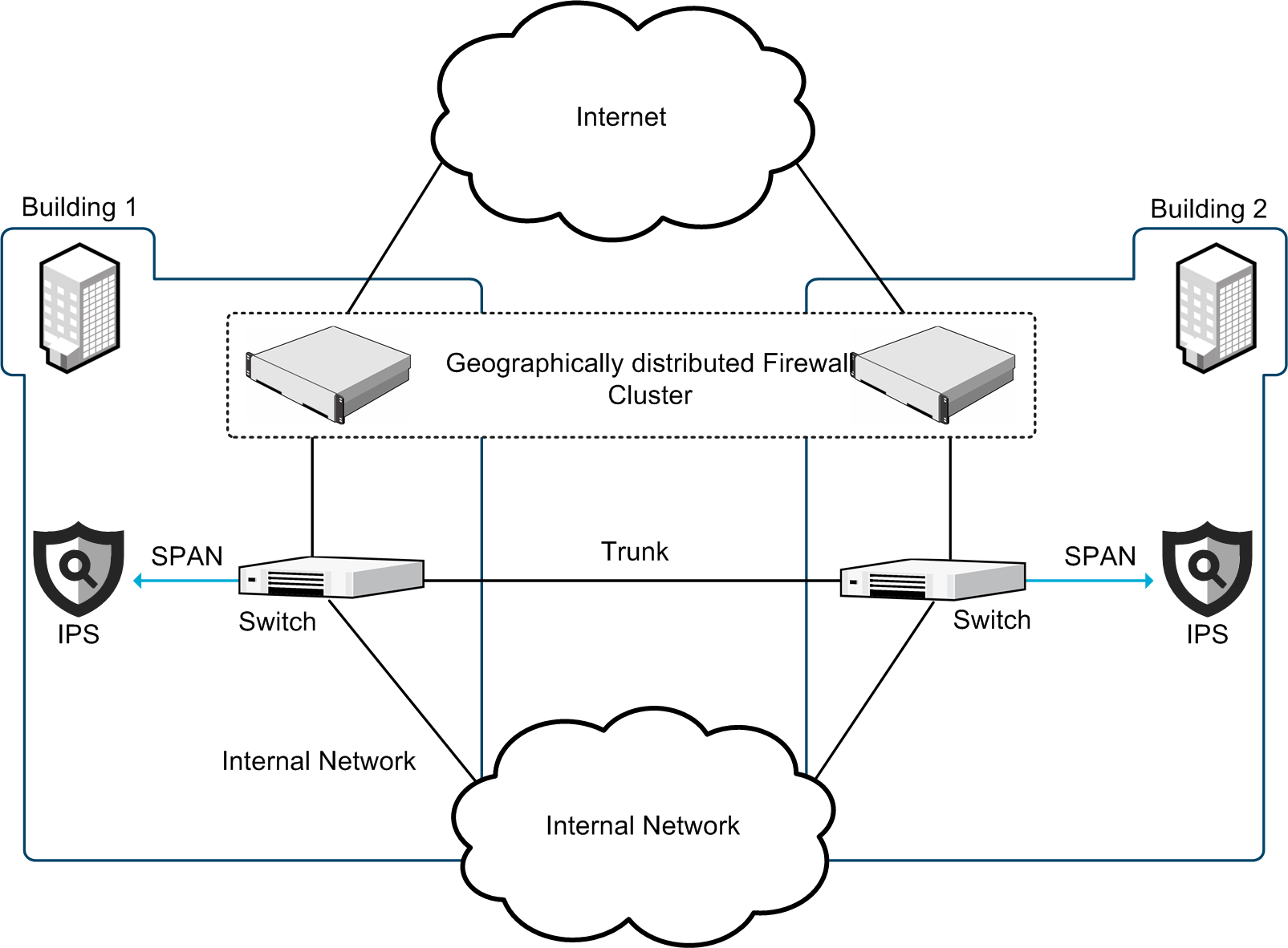
In a redundant disaster-recovery setup, Firewall Cluster nodes can be far apart. The IPS engines are not clustered in this configuration, but they have identical policies.
Figure: Single IPS engines in a distributed disaster-recovery environment