Example: setting up a Firewall Cluster element
An example of creating a Firewall Cluster element and configuring the interfaces.
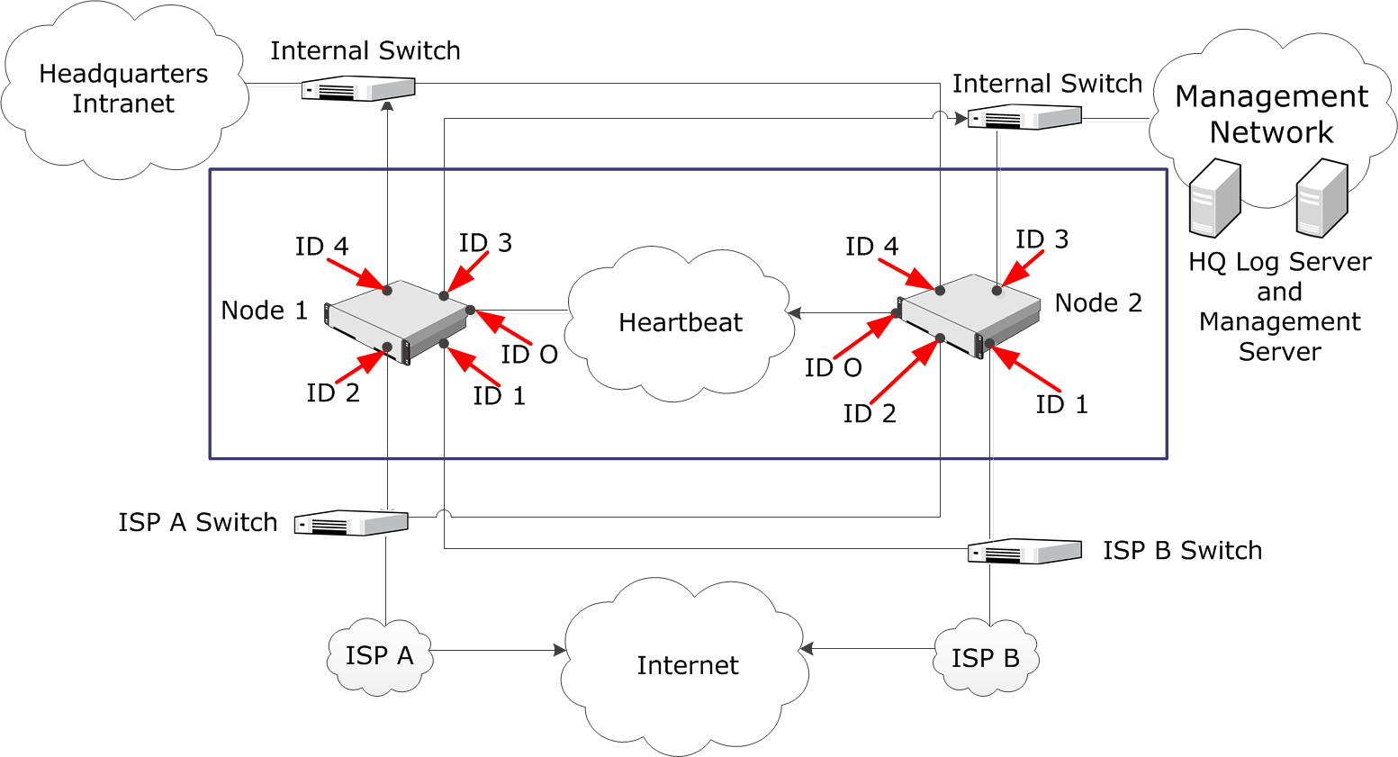
The administrators at the headquarters of Company A want to set up a Firewall Cluster. The cluster consists of two cluster nodes: Node 1 and Node 2. The HQ Cluster Firewall has a dedicated heartbeat network (10.42.1.0/24), and it is connected to two internal networks: Headquarters Intranet (172.16.1.0/24) and Management Network (192.168.10.0/24). It uses Multi-Link to ISP A and ISP B for its connection to the Internet.
Figure: Headquarters Network
The administrators:
- Create a Firewall Cluster element (HQ Cluster) and define HQ Log as its Log Server.
- Define the physical interfaces 0–4.
- Define the CVIs and NDIs for the physical interfaces. Except for the IP addresses, the node-specific properties for Node 1 and Node 2 are the same.
Table 1. Cluster Interfaces Interface ID Type IP Address Comment 0 NDI for Node1 10.42.1.1 Heartbeat 0 NDI for Node2 10.42.1.2 Heartbeat 1 CVI 129.40.1.254 ISP B 1 NDI for Node1 129.40.1.21 ISP B 1 NDI for Node2 129.40.1.22 ISP B 2 CVI 212.20.1.254 ISP A 2 NDI for Node1 212.20.1.21 ISP A 2 NDI for Node2 212.20.1.22 ISP A 3 CVI 192.168.10.1 Management Network 3 NDI for Node1 192.168.10.21 Management Network 3 NDI for Node2 192.168.10.22 Management Network 4 CVI 172.16.1.1 Headquarters Intranet 4 NDI for Node1 172.16.1.21 Headquarters Intranet 4 NDI for Node2 172.16.1.22 Headquarters Intranet - Save the initial configuration of the engines in the Management Client.
- Map the interface identifiers in the configuration to the physical interfaces on each engine’s command line and establish contact between each engine and the Management Server.
- Install a Firewall Policy on the Firewall Cluster in the Management Client to transfer the working configuration to the firewall engines. The nodes exchange authentication information and begin to work as a cluster.