Example: creating a policy-based VPN that requires NAT
An example of a policy-based VPN where NAT is used to translate between its internal and external IP addresses.
Company B has decided to partner with Company C for a large project. Since the companies need to exchange sensitive information, they decide to establish a VPN.
The external gateway device is behind a NAT device that translates between its internal and external IP address. Both addresses are needed in the policy-based VPN configuration.
Both companies also use the same address space internally, so they must apply NAT for all connections through the policy-based VPN as well.
Figure: NAT for a policy-based VPN between two gateways
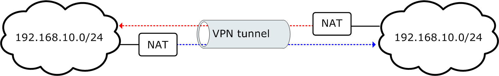
NAT is applied at both companies before traffic enters the VPN from each end. Routing problems caused by the same address space appearing in two different networks can be avoided, since traffic that is routed into the VPN uses unique translated addresses.
- Edit the firewall element and select the engine’s public IP address as the VPN endpoint.
- Create a Location element and select it for their firewall element.
- Create an External VPN Gateway element called “Partner Gateway” for the partner’s VPN device and configure the following IP addresses:
- Select the internal IP address as the VPN endpoint.
- Add the external (translated) IP address as the Contact Address for the Location created in the previous step.
- Create a Network element called “HQ NAT Address Space” for the addresses that Company B plans to use for translating their internal IP addresses. They make sure that these addresses are routable and unique in Company C’s internal network.
- Add only the Network element created in the previous step in the Site for the NGFW Engine.
- Create a Network element called “Partner Network” for the addresses that Company C plans to use for translating their internal IP addresses. They make sure that these addresses are routable and unique in Company B’s internal network.
- Add the “Partner Network” as the only network in the Partner Gateway’s Site.
- Create a VPN Profile and make sure all settings match the settings agreed with Company C.
- Create a Policy-Based VPN element called “Partner VPN” that includes the VPN Gateway that represents the NGFW Engine as a central gateway and the External VPN Gateway as a satellite gateway.
- Add the following types of Access rules in the policy of their firewall:
Source Destination Action Network element “Partner Network” Network element “HQ NAT Address Space” Use VPN - Enforce “Partner VPN” Company B’s internal network (real IP addresses) Network element “Partner Network” Use VPN - Enforce “Partner VPN” - Add the following types of NAT rules in the same policy:
To make the static address translation work, the administrators make sure that the translated address space is as large as the original address space.
Source Destination Action Company B’s internal network (real IP addresses) Network element “Partner Network” Static source translation to “HQ NAT Address Space”