Example: IPS Capture Interface configuration with TAP
An example of using a network TAP device to forward packets for inspection.
The administrator at company B wants to set up a Single IPS engine and deploy it in IDS configuration using a network TAP device. WireTAP copies transmitted (Tx) and received (Rx) packets from the monitored cable and forwards them to separate links for further analysis in the Single IPS engine. The following illustration shows the interfaces of the Single IPS engine in IDS configuration.
Figure: Capture Interfaces with TAP
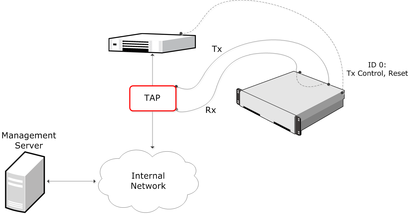
In this example, Interface ID 0 is a Normal Interface used for management connections, and sending TCP Reset responses. Interface ID 1 is a Capture Interface that listens to the received (Rx) packets from the network TAP. Interface ID 2 is a Capture Interface that listens to transmitted (Tx) packets from the network TAP. Interface IDs 1 and 2 share the Logical Interface, which combines the traffic from both physical interfaces so that it can be inspected as a complete traffic flow.
The administrator does the following:
- Creates a Single IPS element, and selects the Log Server to which it sends log data and the traffic recordings.
- Creates a Logical Interface called Capture for the two Capture Interfaces.
- Defines Interface ID 0 as a Normal Interface and adds an IP address to it.
- Defines Interface ID 1 and Interface ID 2 as Capture Interfaces, selects Interface ID 0 as the Reset Interface, and selects the Logical Interface called Capture for both.
- Saves the initial configuration of the engine in the Management Client.
- Connects the network cables to the appropriate NICs.
- Maps the interface IDs to the physical interfaces in the NGFW Initial Configuration Wizard and makes initial contact with the Management Server.
- Installs an IPS Policy in the Management Client to transfer the configuration to the engine.