Example: IPS Inline Interface configuration
An example of deploying a Single IPS in the traffic path.
The administrator at Company C wants to set up a Single IPS engine and deploy it in the traffic path. The following illustration shows the interfaces of the inline Single IPS engine.
Figure: Inline IPS engine
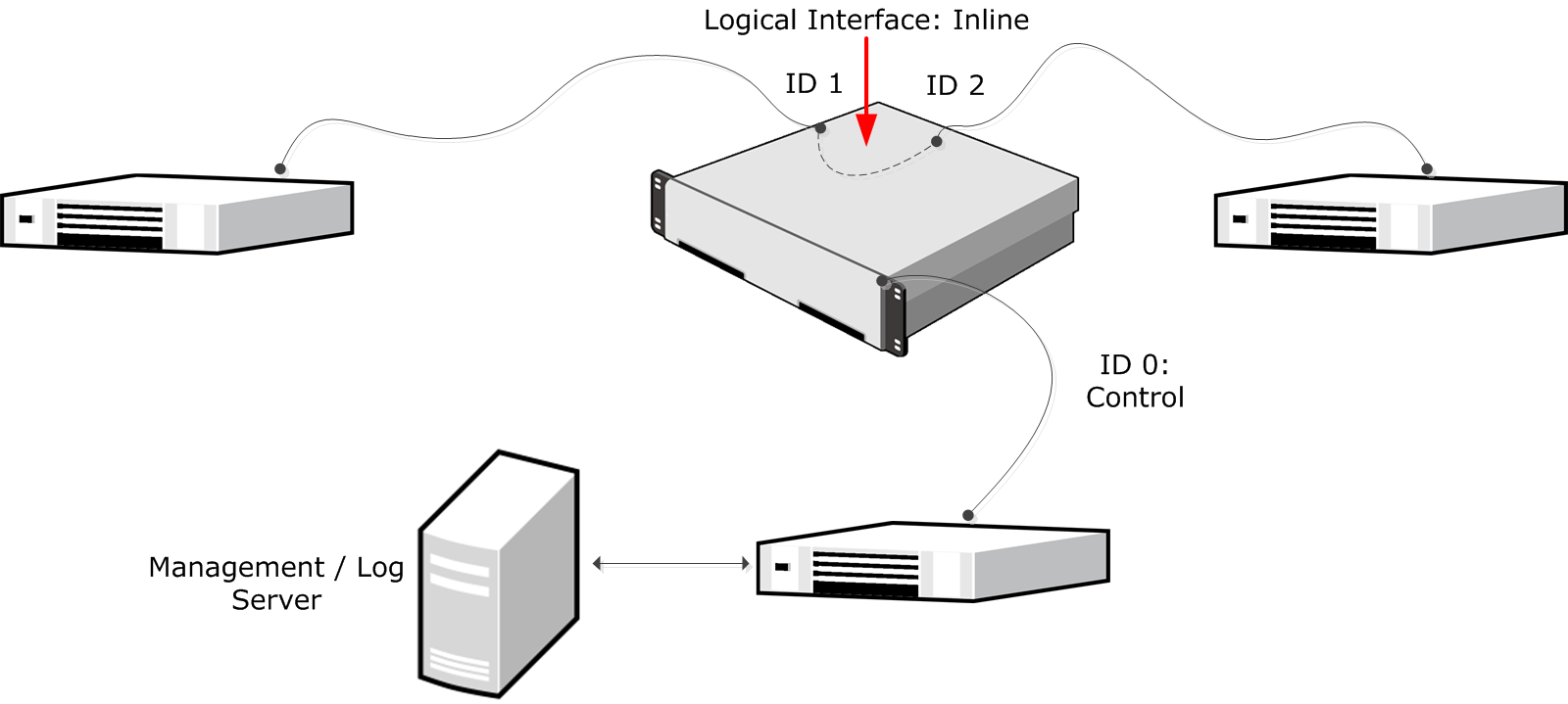
In this example, the IP address on Interface ID 0 is configured as the Control IP address for management connections. Interface ID 1 and Interface ID 2 are an Inline Interface pair that share the Logical Interface, called Inline. Traffic comes in through Interface ID 1. Any traffic that is allowed by the IPS engine leaves through Interface ID 2.
The administrator does the following:
- Creates a Single IPS element and selects the Log Server to which it sends log data and the traffic recordings.
- Creates a Logical Interface called Inline for the Inline Interface pair.
- Defines Interface ID 0 as a normal interface and adds an IP address to it.
- Defines Interface IDs 1 and 2 as an Inline Interface pair and selects the Logical Interface called Inline for the pair.
- Saves the initial configuration of the engine in the Management Client.
- Connects the network cables to the appropriate NICs.
- Maps the interface IDs to the physical interfaces in the NGFW Initial Configuration Wizard and makes initial contact with the Management Server.
- Installs an IPS Policy in the Management Client to transfer the configuration to the engine.